English
 中文简体
中文简体 русский
 Español
Home / Blog / Industry News / Ultrasonic Welding of Plastic: Process, Materials, Joint Design and Machine Selection


Request A Quote

Plastic parts that come out of an injection mold are not always ready for their final use. They usually need to be joined to another component. Pressure testing, drop testing, and daily field use expose every weak bond. Adhesives add weight and chemical complexity. Fasteners create stress concentrations. Heat staking is slow. Ultrasonic welding of plastic, on the other hand, makes a strong, clean bond in a fraction of a second by vibrating the material at the interface until it melts and fuses.
This method is widely used in packaging, medical devices, automotive interiors, and electronics because it needs no consumables, produces no smoke, and leaves no visible marks. Yet it is not a universal cure. It depends on three things: the polymer must be weldable, the joint must be designed for the process, and the welding machine must deliver controlled mechanical vibration at the right amplitude and frequency. When those conditions are met, ultrasonic welding is one of the most cost-effective plastic joining methods available.
Content
The operating principle is simple when you separate it from the hardware. A power supply turns normal line voltage into a high-frequency electrical signal. That signal drives a transducer, which converts the electrical pulse into mechanical vibration at 20 kHz, 35 kHz, or 40 kHz. The vibration passes through a booster to adjust amplitude, then reaches the welding horn. The horn presses the two plastic parts against their fixture and transfers the vibration directly to the joint.
At the contact interface, the high-frequency motion causes intermolecular friction. This friction rapidly increases the temperature just enough to melt the plastic without burning it. Because the heat is localized, the surrounding material remains solid and dimensionally stable. After the weld time finishes, the molten layer cools and solidifies to form a continuous bond.
A typical welding cycle has four phases:
The main components are the power supply, the transducer, the booster, the horn, and the fixture. The power supply maintains a stable amplitude. The booster can magnify or reduce the vibration. The horn distributes it to the part. The material of the horn affects its durability. Titanium horns resist wear in high-volume production, while aluminum horns are common for lighter processes because they are easier to machine.
The key to success is repeatability. Weld time, hold time, trigger force, and amplitude must be controlled to within tight tolerances. If the clamp fixture moves, the horn misaligns, or the power supply drifts, the bond quality changes. That is why the mechanical system around the horn is just as important as the horn itself.
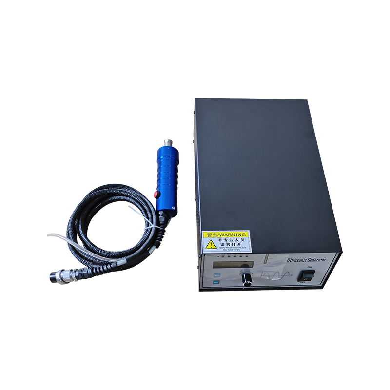
For repair stations, prototype work, or flexible production cells, handheld ultrasonic welders offer the same basic mechanism in a portable package. They let an operator move the horn to the part instead of moving the part to the machine.
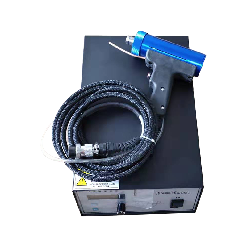 Portable 28kHz/35kHz Ultrasonic Spot Welder for Thermoplastic PartsThis handheld welder suits repair stations and low-volume prototyping. It welds thin sheets and wires without filler, making it ideal for non-woven fabrics, nylon, PP, PE, and PC plastics.View Product →
Plastic selection drives the welding strategy. Amorphous thermoplastics such as ABS, acrylic, and polycarbonate transmit ultrasonic vibration well because they have a broad softening range. They melt gradually and flow without sudden crystallization. Semicrystalline polymers such as nylon, acetal, and polypropylene have a sharp melting point. They need more energy, a well-designed joint, and often a shorter weld time to avoid burns.
Compatibility between parts is another decisive factor. Two parts made of the same polymer usually weld without difficulty. Dissimilar polymer combinations require the same base family. ABS to polycarbonate can work in limited cases with tight process control. ABS to nylon, PVC to polycarbonate, or polypropylene to acetal do not form a stable weld because the thermal properties and molecular structures are too different.
Additives also change the behavior. Glass fiber, mineral fillers, flame retardants, pigments, and lubricants all affect the transmission of energy to the joint. A high percentage of filler can make the joint brittle or prevent proper melt flow. If you are working with a filled material, prototype the joint early and test the actual weld strength before you design the tooling around it.
The table below offers a simple starting point for common thermoplastics.
| Material | Weldability | Typical Use |
|---|---|---|
| ABS | Excellent | Housings, connectors |
| Acrylic | Good | Displays, medical devices |
| Polycarbonate | Good | Lenses, electrical parts |
| Nylon | Moderate | Gears, structural parts |
| Polypropylene | Moderate | Containers, caps |
| PVC | Limited | Pipe fittings, profiles |
Before you commit to a high-volume production run, weld test coupons in the same material and with the same joint design. Check the strength by pulling the joint apart. Also inspect a cross-section under a microscope. This reveals trapped air, unfilled channels, or excessive flash that are not obvious from the outside. It is a small investment that prevents expensive surprises on the line.
For more details on the limitations of specific polymers and practical examples, read our article on ultrasonic welding ideal materials and limitations.
Joint design is the most important factor that determines whether a weld will hold in production. The three main designs are energy director, shear joint, and tongue-and-groove.
An energy director is a small triangular bead molded onto one part. It concentrates ultrasonic stress, melts first, and fills the gap between the mating surfaces. This design works best on flat, rigid parts made of amorphous polymers. For a typical 1.5 mm wall, the energy director should be about 0.3 mm high and 0.4 to 0.6 mm wide. However, the exact dimensions depend on the part thickness and the material.
A shear joint is an interference fit between a male and female section of the parts. It creates a large contact surface and is ideal for semicrystalline materials that need a longer cooling time. The fit also prevents the molten plastic from escaping outward, which reduces flash. Typical tolerances for a shear joint are 0.05 to 0.1 mm.
Tongue-and-groove designs combine alignment with a large sealing area. They can be used as a single wall or double wall, depending on the strength and leak-tightness requirements. A step joint is a simplified version of the tongue and groove and is easier to mold but provides less overlap.
| Joint Type | Best For | Flash Control | Alignment |
|---|---|---|---|
| Energy Director | Amorphous plastics | Moderate | Fair |
| Shear Joint | Semicrystalline plastics | Good | Excellent |
| Tongue and Groove | High-strength assemblies | Excellent | Excellent |
A few practical rules make joint design easier to manage. Never let the horn contact a non-weld rib or a cosmetic surface. Keep the energy director centered over the weld wall. Use a generous draft angle on the male part of a shear joint so the insertion force does not damage the part. Finally, round the edges of the horn to avoid leaving a visible ring on the part.
In practice, the joint must also match the horn profile and the fixture. If the horn touches a rib or a wall that is not part of the weld, vibration energy will disperse and create loose flash. A thoughtful tooling design keeps the horn contact area small and centered.
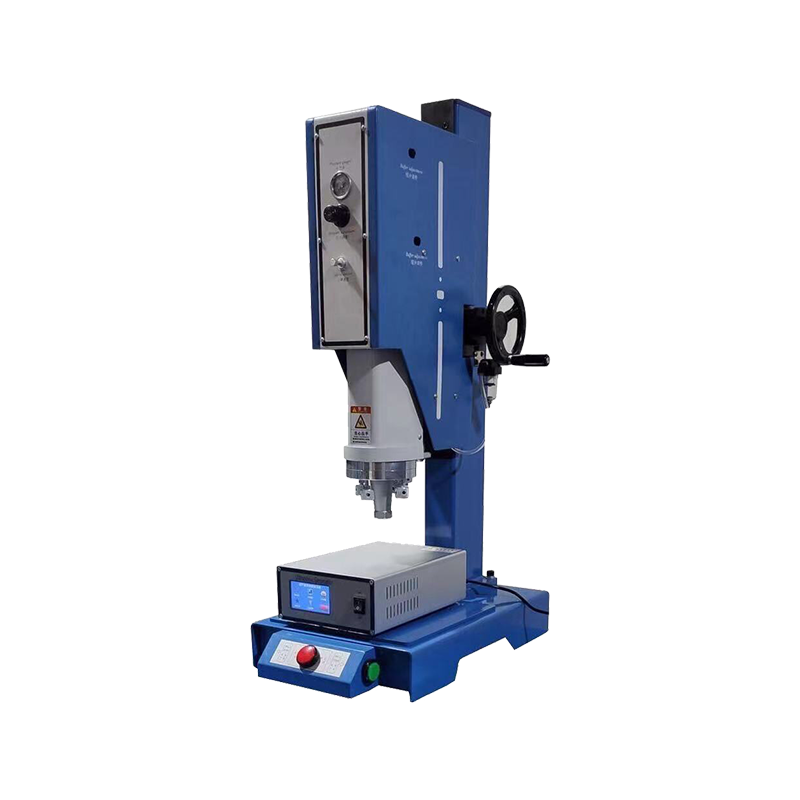
For low-volume runs, manual plastic welding machines give you enough control to work through a few joint variations and find the best settings before moving to automated equipment.
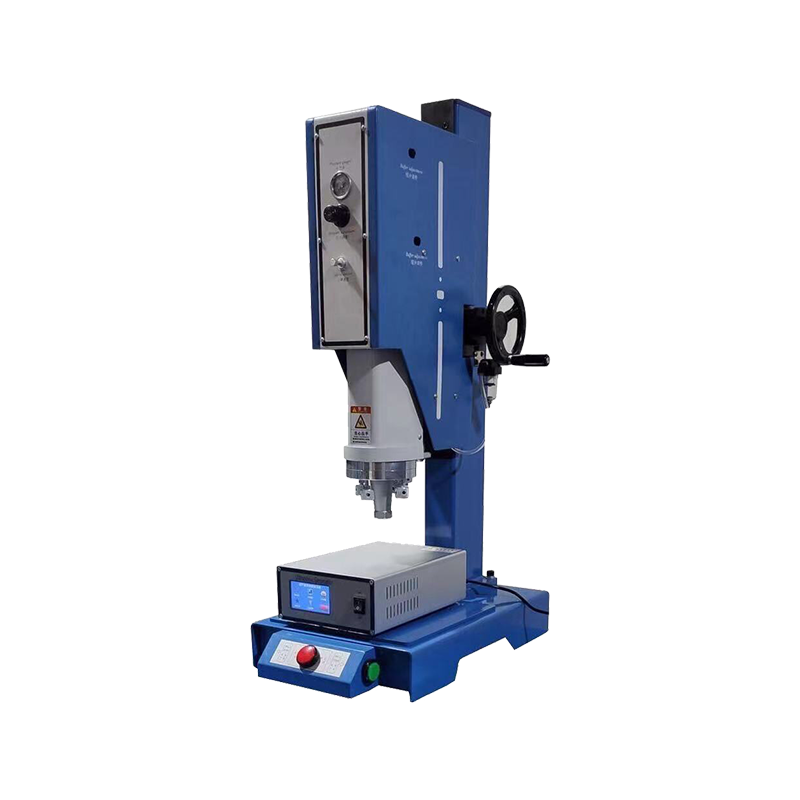 Manual 15kHz Ultrasonic Welding Machine with Adjustable Mold SpaceFor low-volume runs, this manual machine offers precise control over weld time and pressure. It handles spot welding, riveting, and cutting of thermoplastics, helping you optimize parameters before automation.View Product →
Bringing ultrasonic welding from a prototype to a production line starts with parameter optimization. Weld time, hold time, weld pressure, trigger force, and amplitude all need to be matched to the specific part. Many engineers run a small series of parts with varying weld times and then inspect the cross-section to determine optimal weld quality. The energy input is directly linked to weld strength, so it is worth doing this study once the tooling is fixed.
Tolerance is another risk. A joint gap that is too wide absorbs energy and can cause part damage. Too tight a clearance may prevent the horn from seating properly. For shear joints, a 0.05 to 0.1 mm tolerance band is common. For energy directors, the fit can be slightly looser. Remember that the welding process is not a way to correct bad injection molding tolerances. It requires parts that are straight, clean, and consistent.
The welding frequency matters as much as the power. A 20 kHz system with 4200 W provides the energy needed for thick semicrystalline parts. Smaller hand-held units that run at 35 kHz are better for delicate components and thin walls. When choosing equipment, look at the part volume, the material, and your desired cycle time, not just the price tag.
Weld quality should be inspected in every shift. A simple pull test on a sample part tells you whether the bond strength is still within specification. For hermetic assemblies, run a leak test on a regular basis. If you see a sudden drop in strength, stop the line and check the horn, the power supply, and the fixture alignment. It is usually one of these three components that has drifted.
Maintenance is easy to overlook but essential. Horns wear, transducers lose tuning, and fixtures become loose. Worn horns produce irregular amplitude, which creates inconsistent welds. A preventive schedule that includes cleaning, checking horn flatness, and testing transducer continuity will protect uptime and reduce scrap rates.
Finally, consider the operator. A machine that is simple to set up and safe to use will be more productive on a real shop floor. Check that the power supply has clear controls for time and pressure, that the safety switch is reliable, and that you have quick access to spare parts such as welding molds and horns. A capable supplier will also help you evaluate the fixture and the horn design for your exact part.
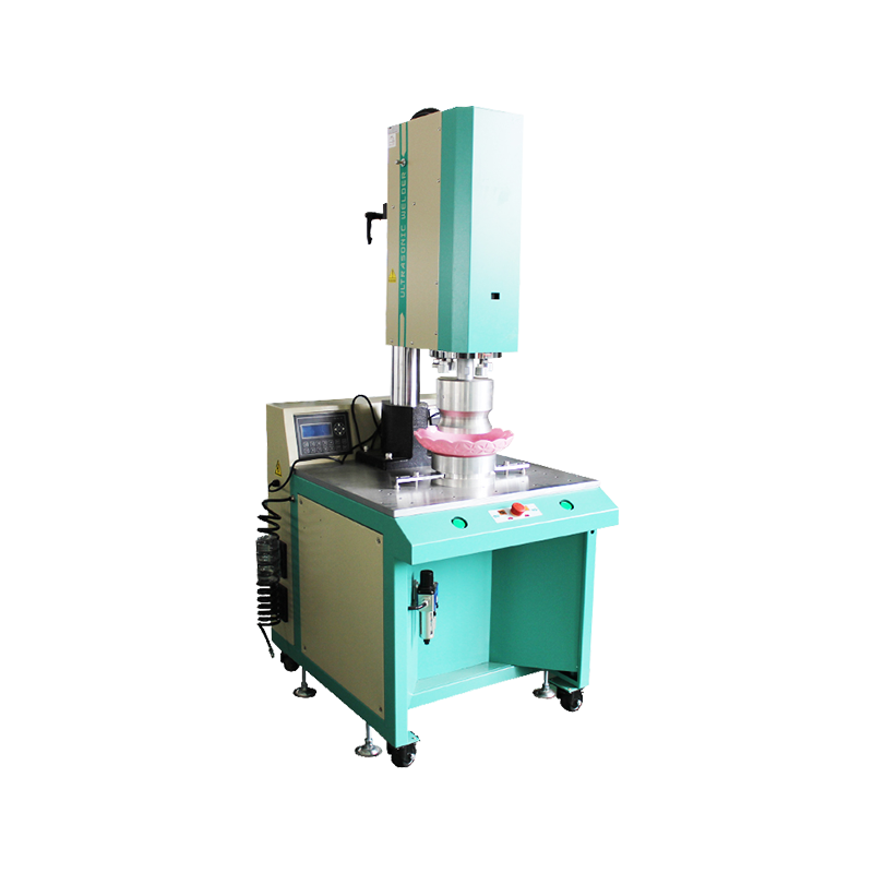
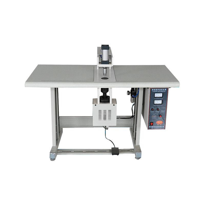
For large, rigid components or heavy semicrystalline sections, a higher-power, low-frequency plastic welding machine is often the best choice.
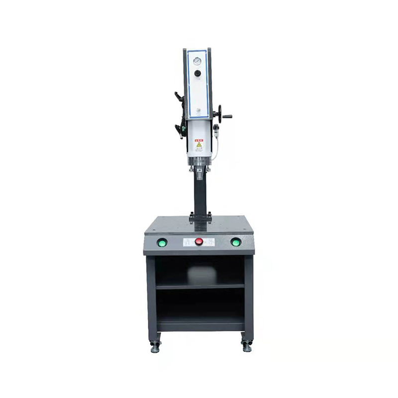 High-Power 15kHz 4200W Ultrasonic Welder for Heavy Semicrystalline PartsThis 15kHz welder delivers 4200W for large rigid components and heavy semicrystalline plastics. It supports time, manual, and energy modes, with CNC-machined frame for stable force and precise joints.View Product →
Copyright © ChangZhou AoHeng Machinery Co., Ltd. All Rights Reserved